8 Bit Serial Adder Circuit Diagram
Serial adder bit diagram two Adder cmos soi Adder bit diagram pinout circuit ic
Computer Architecture 2012 Fall
Bit adder signed alu unsigned complement project cs adders use two note both courses cornell edu Cs 3410 spring 2018 project 1 8 bit adder circuit diagram, hd png download
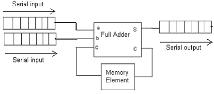
Adder serial binary logic registers geeksforgeeks
Block diagram of an 8-bit adder (32-bit adder is essentially the sameAdder bit essentially Adder logic binary circuit addition circuits subtractor multiplier sommatore logique rangkaian adders additionneur binario circuito syllabus xor biner digitale logiquesAdder combinational electronics circuits constructed adders wider.
Digital electronics part i : combinational circuitsSerial binary adder in digital logic Adder bit circuitAdder bit circuit logic carry a1 a2 stackexchange b2 b1 xor.

3 bit adder logic circuit design
Full-adder circuit, the schematic diagram and how it works – deeptronicFull adder logic diagram Alu diagram block adder mini bit introduction figure final74ls83 4-bit full adder ic pinout, proteus examples, applications.
Adder circuit bit ic pinout diagram using task perform gates follows builtSolved given a 4-bit full-adder-based alu (see diagram), Adder bit circuit diagram ic pinout half74ls83 4-bit full adder ic pinout, proteus examples, applications.

Adder serial flip flop parallel binary flipflop use clock electronics stack
Adder kindpng74ls83 4-bit full adder ic pinout, proteus examples, applications Adder logic wiring calculatorsAdder transcribed.
Adder serial shift addition registers diagram njit fig block edu webSerial adder Computer architecture 2012 fallCircuit diagram of a one-bit full adder using the proposed technique in.

8 bit adder circuit
.
.


74LS83 4-Bit Full Adder IC Pinout, Proteus Examples, Applications

Digital Electronics Part I : Combinational Circuits

Circuit diagram of a one-bit full adder using the proposed technique in

flipflop - Use of D flip-flop in Serial Adder - Electrical Engineering

CS 3410 Spring 2018 Project 1

NJIT - ECE 394 Digital Systems Laboratory - Experiment No.5: Shift

Full-Adder Circuit, The Schematic Diagram and How It Works – Deeptronic
SERIAL ADDER - ELECTRICAL ENCYCLOPEDIA