556 Pwm Controller Circuit Diagram
556 timer diagram internal dual circuit ic schematic elektropage inside block Electronics components: double up with the 556 dual timer 555 pwm astable circuit circuits signal between ic functional difference various arduino timer generate next nidec pot topic electrical stack
FEEE - Fundamentals of Electrical Engineering and Electronics: PWM
Pwm controller ic ungrounded grounded load 2010 circuit rust july frequency Timer 556 schematic components double dummies implemented nearly identical Pwm multisim generator dual
Retriggerable one shot with 556 ic – electronic circuit diagram
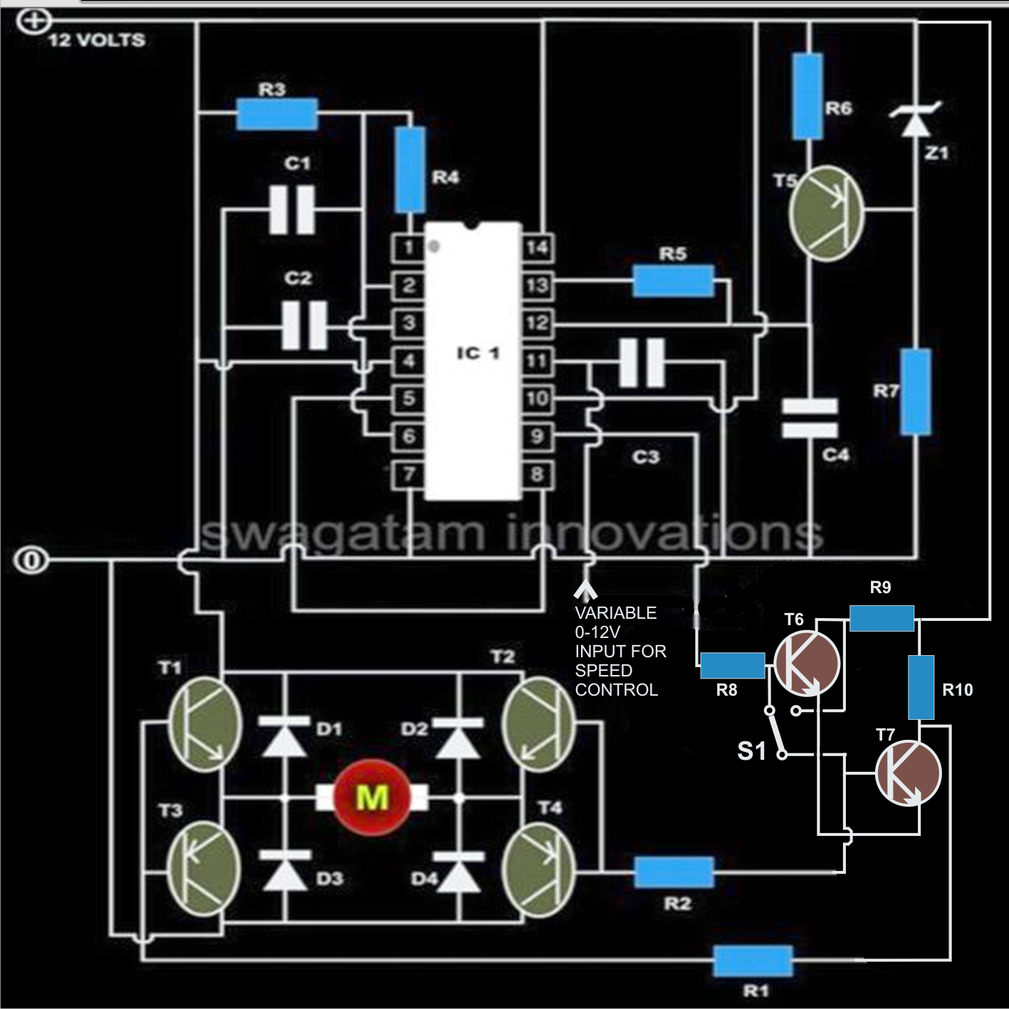
Pwm motor speed controller circuit using ic556Pwm circuit pulse led width motor dc speed modulation schematic variable brightness cycle duty inverter chip control circuits make logic Whirlyworld: dc motor control with 556 timerMotor dc controller control diagram ne555 schematic circuit using circuits speed pwm 12v simple wiring electrical diagrams electronic schematics robotics.
Schematic & wiring diagram: dc motor controller circuit with ne555Timer motor control dc 556 timer timers dummies draw componentPwm 556 timer generator circuit based dual far looks down.

Control a stepper motor using python and a raspberry pi
Pwm slideshare upcomingStepper motor wiring tb6600 nema Timer 556 dual circuit tester diagram sponsored links circuitdiagram556 (dual 555) pwm generator.
555 pulse width modulator (voltage controlled duty cycle)Electronics components: double up with the 556 dual timer Pwm power controller schematic feee circuit diagram illustrationThis is purely a voltage drop and you can consider the voltage drop to.

556 diagram timer connection dual general generator elektropage block circuit description ramp linear
72v 500a 16khz pwm versterkerMotor dc pwm speed control controller circuits diagram simple circuit explained achieve modifications slowest response possible shown few below making 556 dual timer testerModulator pulse multisim.
Pwm 500a 72v 16khz versterker5 simple dc motor speed controller circuits explained Motor speed circuit controller pwm dc using control ic torque constant single features circuits homemadeShot ic rend march.
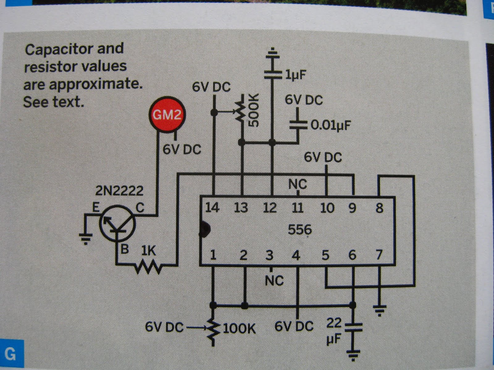
General description and connection diagram of 556 dual timer 556 timers
Circuit relay timer using control diagram toggle seekic556 dual timer internal block diagram the inside of 556 timer ic 556 pwm circuit chip555 ic pwm controller: grounded and ungrounded load – electronic.
Pwm generator based on the 556 dual timer .


72V 500A 16KHz PWM versterker - Forum - Circuits Online

555 IC PWM Controller: Grounded and Ungrounded Load – Electronic
whirlyworld: DC motor control with 556 timer

Index 53 - Control Circuit - Circuit Diagram - SeekIC.com

556 pwm

design - Functional difference between various astable 555 circuits

556 Dual Timer Tester | Circuit Diagram

FEEE - Fundamentals of Electrical Engineering and Electronics: PWM